


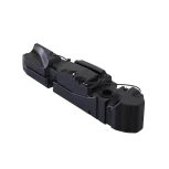
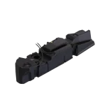
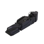

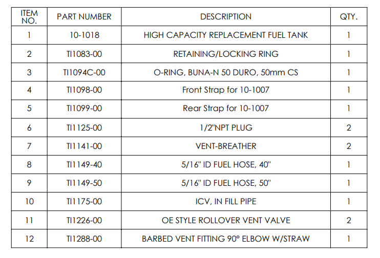
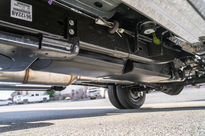
S&B 60 Gallon High-Capacity Fuel Tank (10-1018) for 2005-2012 Cummins 5.9L & 6.7L Crew Cab – Long Bed
$1,449.00
- This tank won’t fit trucks with aftermarket or one-piece drivelines.
- The nozzle at high flow fuel stations(truck stops) will not be able to fill automatically.
- OEM sending unit & float are reused because the S&B Tank is taller the gauge will stay on full for the first 8-10 gallons.
| Weight | 70 lbs |
|---|---|
| Dimensions | 90 × 18 × 18 in |
Fitment
| Year | Make | Model | Engine |
|---|---|---|---|
| 2005-2007 | Dodge / Ram | Ram 2500 | 5.9L, Diesel |
| 2005-2007 | Dodge / Ram | Ram 3500 | 5.9L, Diesel |
| 2007-2012 | Dodge / Ram | Ram 2500 | 6.7L, Diesel |
| 2007-2012 | Dodge / Ram | Ram 3500 | 6.7L, Diesel |
Features
| Compatible with gooseneck and 5th wheel | Yes |
| Compatible with oe skid plate | No |
| Dimensions | 82.31″ X 17.68″ X 18.99″ |
| Drain | No |
| Embedded fitting thread size | 1/2″ NPT |
| Ground clearance compare to oe tank | 2.75″ lower |
| Oem capacity | 35 Gallons |
| Sending unit | OE |
| Straps included | Yes |
| Sump | No |
| S&B Capacity (Approximate) | 60 gallons |
| Tank type | Midship |
| Transfer pump ready | Yes |
| Weight dry | 48lbs |
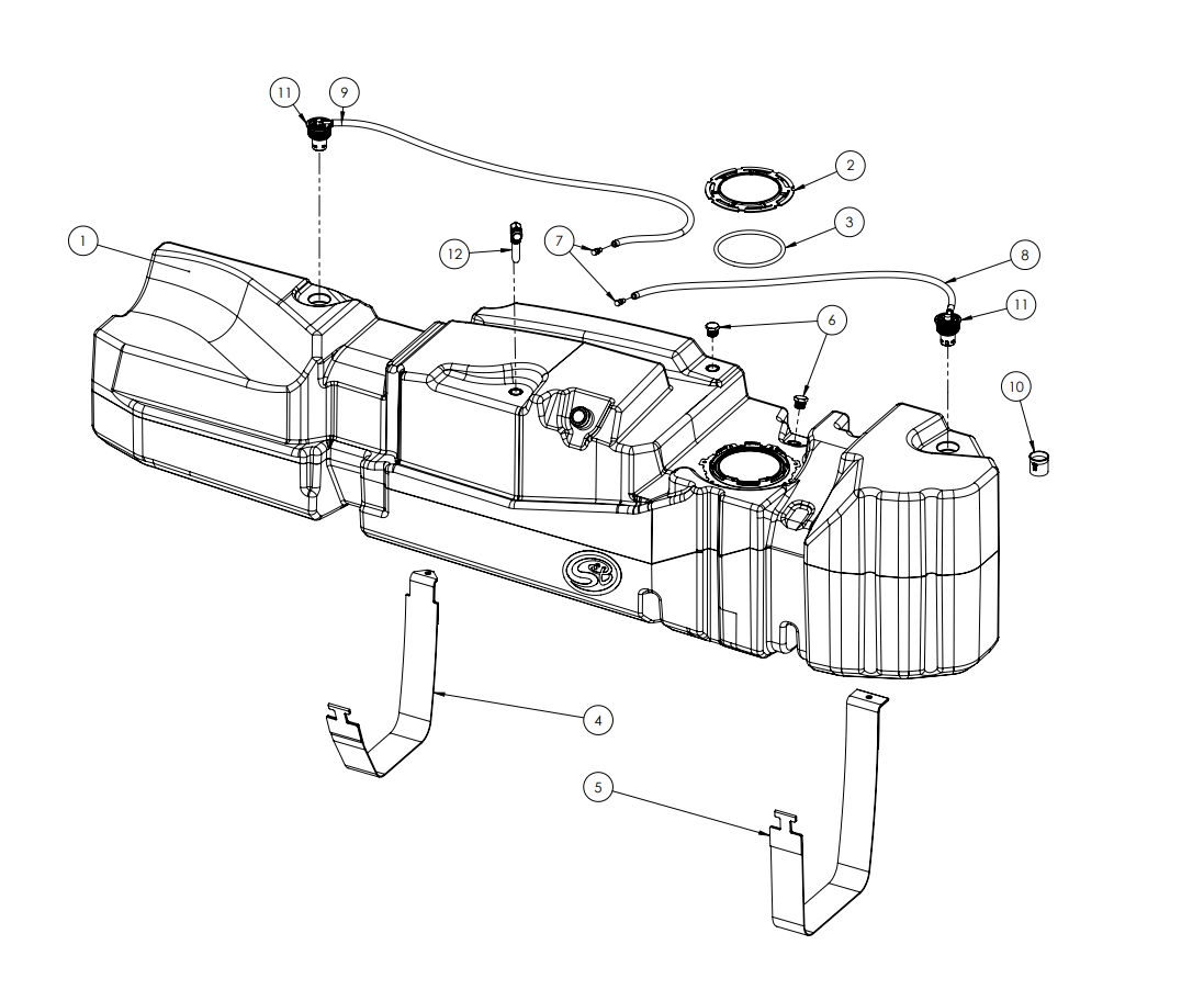
Installation
Before You Start
Please read the entire product guide before proceeding
Ensure all parts are present.
If you are missing any parts, please call or text us at (909)-675-1313
Do not work on your vehicle while the underbody components are hot.
Make sure the vehicle is in park or the parking brake is set if you plan on working on the ground. If working on a lift, make sure the vehicle is lifted safely and securely.
Required Tools
Flathead Screwdriver
Mallet/Hammer
16mm Deep Socket
Ratchet
12″ Driver Extension
STEP 1
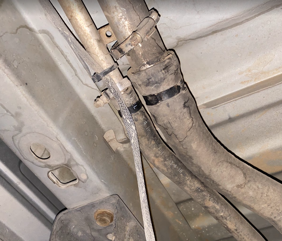
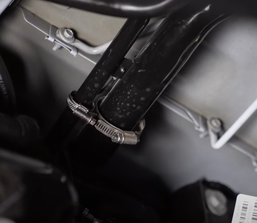
Loosen the hose clamp on the filler and vent hose and remove both rubber hoses from the metal tubes
STEP 2
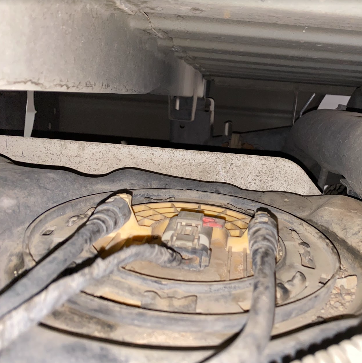
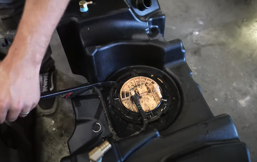
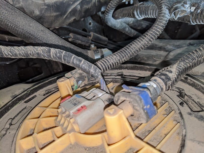
Disconnect the feed line, return line and electrical connector from the sending unit.
STEP 3
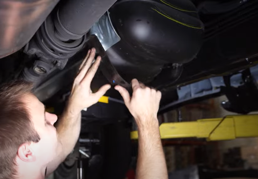
Use a jack to support the tank then use a 16mm socket to remove the nuts from the strap mounting studs.
STEP 4
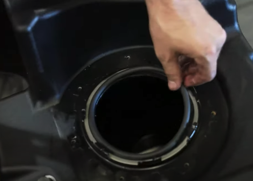
After the tank has been dropped. Remove the OEM fuel sending unit locking ring from the tank by hitting the ring counterclockwise. The OEM o’ring won’t be used again.

STEP 5
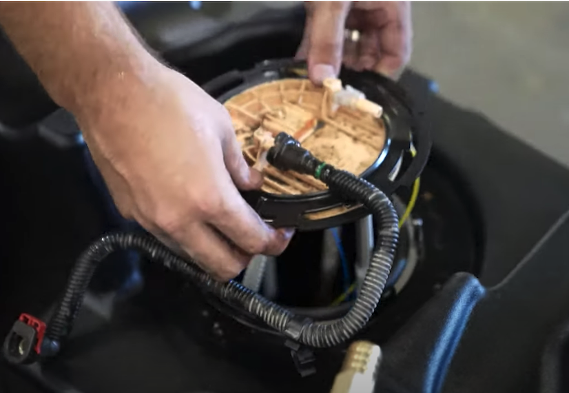
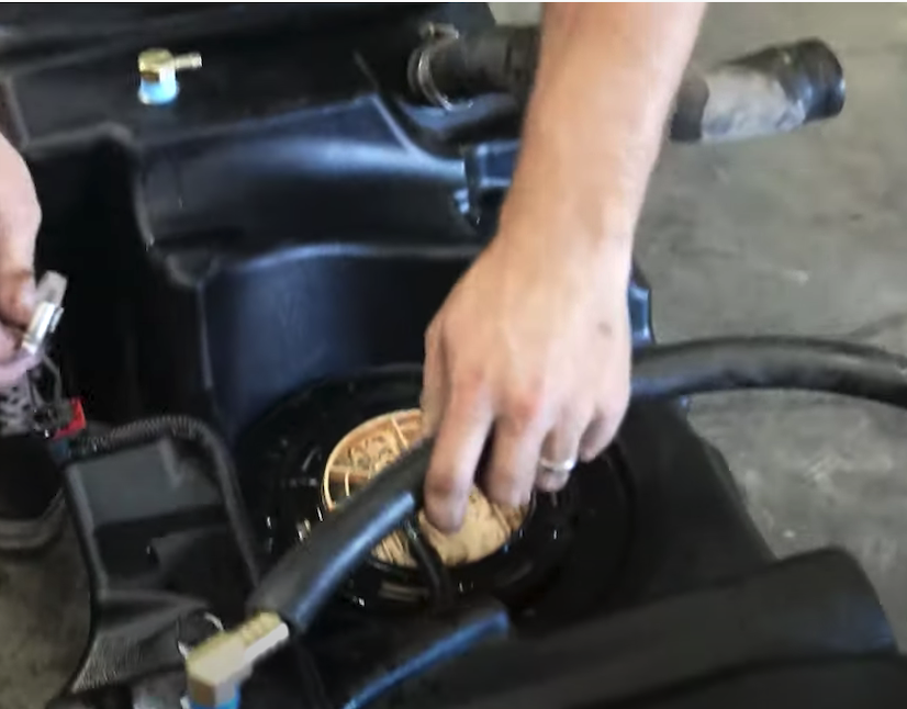
Place the S&B o’ring into the o’ring groove then drop the sending unit into the tank.
STEP 6
If you are working with the truck on a lift place a jack centered under the tank. Remove the OEM fuel tank straps. These are 16mm nuts that hold the straps to the studs. When removing the straps from the frame side, you will need to push the strap up to release the strap from the cradle.
STEP 7
After the tank has been dropped. Remove the OEM fuel sending unit locking ring from the tank by hitting the ring counterclockwise. The OEM o’ring won’t be used again.
STEP 8
Place the S&B o’ring into the o’ring groove then drop the sending unit into the tank.

STEP 9
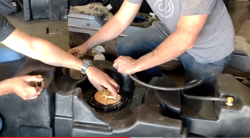
Drop in the OEM sending unit into the S&B Tank. The retaining ring included with the tank will be used.
STEP 10
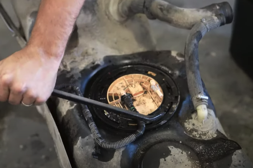
Place the included locking ring over the sending unit flange. First, by pressing down on the ring, get the ring started under the teeth on the tank. Once started, hit the ring clockwise until it passes under the indentation on tank teeth
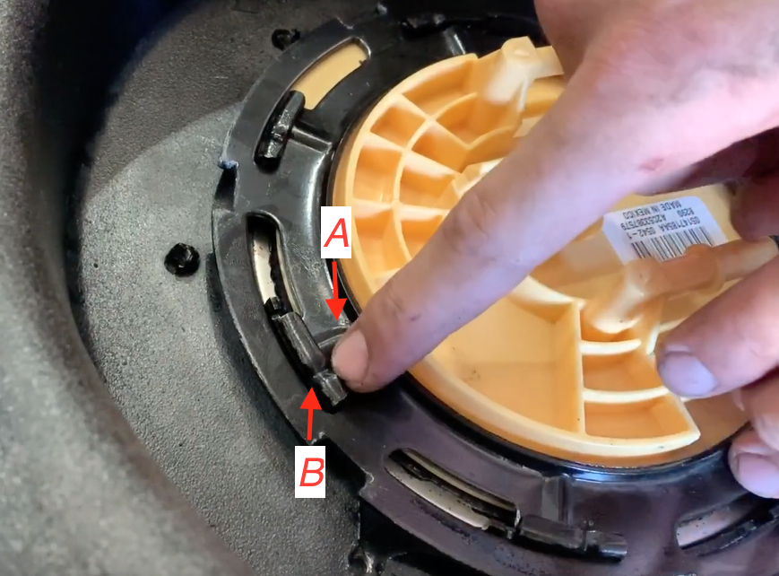
STEP 11
Ensure the locking ring is fully rotated until the rib on the OEM locking ring(point A) is PAST the indentation on the S&B receiving ring(point B).
STEP 12
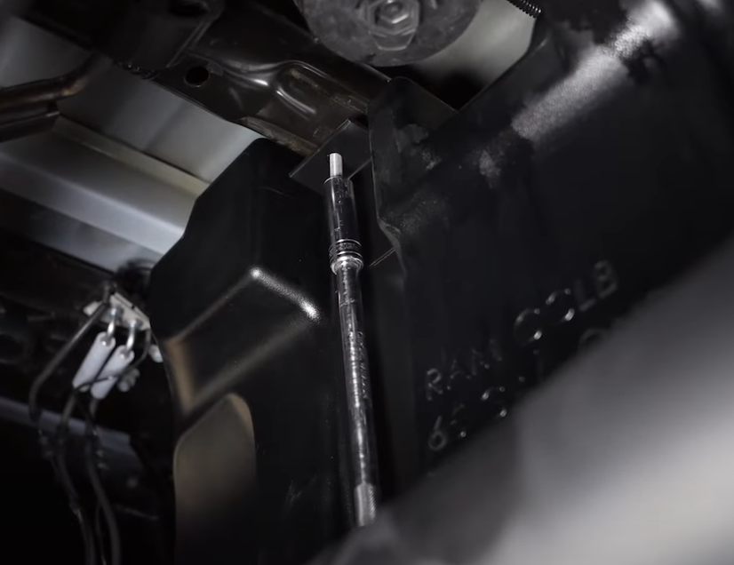
Poke a small hole in the rubber cap covering the filler spout on the S&B Tank, block off the openings in the tank with electrical tape or cover with fingers, spray the sending unit o’ring area with soapy water and pressure test the tank to make sure the o’ring was properly seated and there are no leaks in the tank.
STEP 13A
Transfer over the fill hose and put in onto the S&B Tank. Take the vent hose clamp from the OEM tank and reuse this hose clamp with the S&B vent line.
STEP 13B
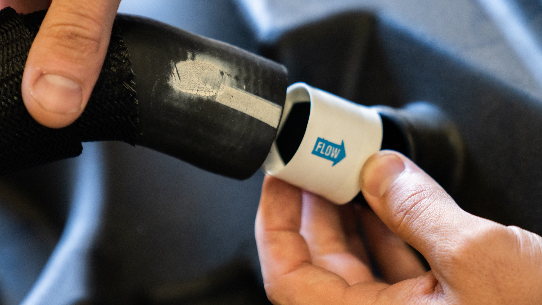
Before putting the filler hose onto the tank, place the white check valve into the filler hose with the blue arrow facing into the tank opening
STEP 14A
Lift the tank up into position making sure the vent and fill hose goes over the frame. Then install the front and rear straps. The strap bend on the frame side will need to be straightened out to be able to get the strap hooks into the frame. Push the strap hole through the stud on the driveline side and get the nut started. If the fill and vent lines are over the frame and the electrical connectors are free you are fasten the nuts onto the studs then you are ready to tighten the straps
STEP 14B
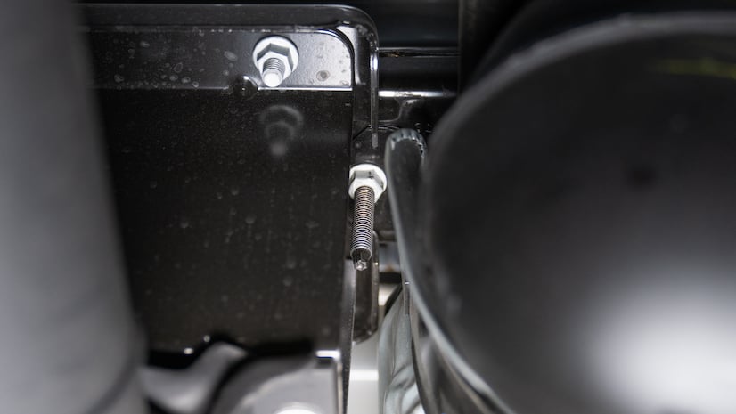
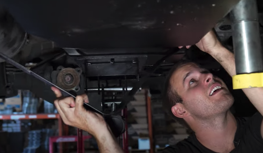
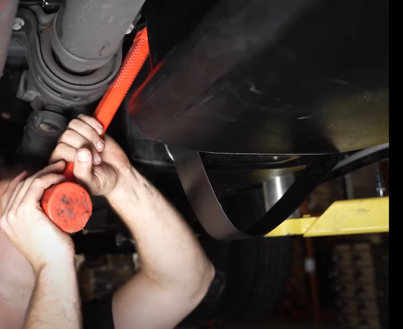
Use the end of a rubber mallet or pry bar to pass the strap past the carrier bearing mount
STEP 14C
Tighten the OEM nut to the stud and double check to make sure it is secure (45 ft. lbs).
STEP 15
Reconnect the feed line, return line and electrical connector. Make sure the connectors are locked. To make sure they are locked, gently pull on the connectors to make sure they won’t come off and are locked in.
STEP 16
Reinstall the hose clamps on the fill and vent lines.
STEP 17
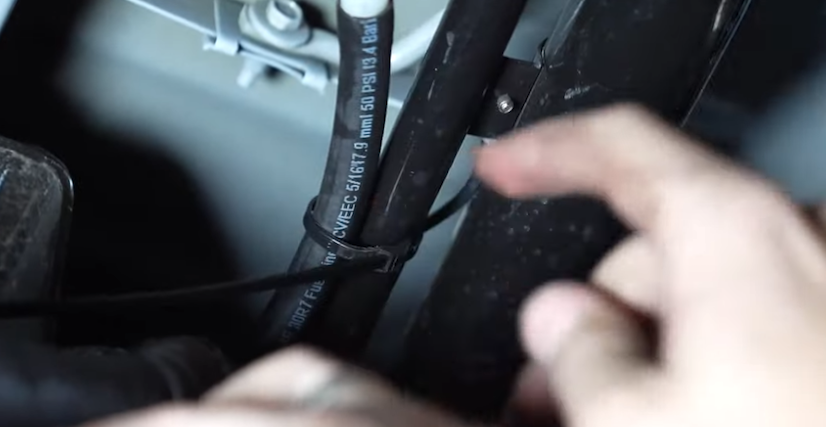
Zip tie the S&B front and rear rollover valve hoses to the filler neck. Once this step is complete, you are ready to put fuel into the tank. Please review the checklist below to make sure you did not forget anything and that the tank is installed properly.
Step 18 FINAL CHECKLIST
This final checklist is very important.
#1 Make sure all nuts are safely fastened and torqued.
#2 Ensure there is proper driveshaft clearance and the straps are tight
#3 Double check fuel line connections, the electrical connection as well as the vent and fill lines.
#4 Lastly, fill the tank full and check for any leaks.
If you have any questions, call or text us at 909.675.1313
You must be logged in to post a review.
Related products


Reviews
There are no reviews yet.